Activity
Mon
Wed
Fri
Sun
Aug
Sep
Oct
Nov
Dec
Jan
Feb
Mar
Apr
May
Jun
What is this?
Less
More
Memberships
PCB Design Skool
181 members • Free
Hardware Engineer Accelerator
126 members • $9/month
Fresuelectronics.com
1.6k members • Free
3 contributions to Fresuelectronics.com

Oct '25 •
EMC/EMI Control Guide Series – Today FREE…
Yesterday, we launched new tiers for the FresuElectronics Academy. To celebrate the event and thank our new members, I’m giving the EMI Control Series Guides (normally paid) for FREE to anyone who joins the Academy today. This eBook bundle combines three powerful guides I developed to help engineers stop EMI problems and build electronic systems and PCBs that meet FCC and CE standards easily. These proven methods have been used to fix EMI issues, avoid design mistakes, and pass EMC tests, keeping electronics projects running smoothly. Inside this bundle, you will learn: - The key EMC/EMI problems in electronic design and how to solve them. - The best strategies to prevent EMI and handle EMC test failures. - How to apply EMI fixes from start to finish in any project. Interested? Join the Academy here: https://fresuelectronics.com/academy To electromagnetic enlightenment, Dario P.S. Don’t wait until tomorrow to join. This is a limited-time offer.

1 like • Oct '25
Hi Dario, When I first joined tomorrow the Akademi, I noticed that all the resources were already available. I thought this was a special gift for us for the opening, and I was really thrilled! Thank you so much for your generous gifts. 😊 Now I can access all the modules, and I just hope they won’t be “closed for renovation” anytime soon 😄. Best regards,
1 like • Oct '25
Thanks for the clarification, Dario! 😉 Now I understand why I felt like I was in a “parallel universe” 😄. I’ll make sure to switch communities and explore the new ones!

Sep '24 •
Decoupling capacitores Values
I have read in many CMOS IC datasheets that the typical values for decoupling capacitors are 100 nF, but on the other hand I have read an article by Eric Bogatin stating that this is a false myth and that this has been going on since the 80's when CMOS IC voltages were much lower. Actually he refers to calculate the decoupling capacitors with respect to the CMOS frequency and their rise times. Could someone clarify me which is the correct way of sizing the decoupling capacitors and the technical reasoning why? I would like to clear this doubt and when I search the internet I see disparity of opinions. thanks. Translated with DeepL.com (free version)
1 like • Oct '25
Hello everyone, I apologize for commenting a bit late, as I have just joined the group. I recently finished the Power Delivery Networks course, and like Ivan Mendez alonso, I find some parts quite confusing. So far, I have mostly selected decoupling capacitors based on reference designs. However, I learned in the course that this approach is not always correct; capacitor values should be calculated properly and ideally be the same. I’m particularly struggling with the calculation part.To determine the target impedance, I need to consider the transient current. I tried using the formula: I transitent= n*Cpd*Vcc/Tr The datasheet only specifies Pin Capacitance = 2 pF, and I could not find information about tr. Therefore, I could not calculate the target impedance. Also, the 2 A value used in Ivan Mendez alonso example seems quite high to me, and I’m not sure where this value should come from. Using approximate values, my calculations indicate that theoretically, a very large number of capacitors would be required. However, placing so many capacitors would significantly lengthen the routing and negatively impact ESL. My question is: How can I translate this theoretical capacitor calculation into a practical PCB design? In other words, theory suggests a large number of capacitors, but how can we manage placement and routing lengths in practice? I would greatly appreciate any advice or experiences you can share. Thank you in advance.
0 likes • Oct '25
Sorry Dario, I am level 2 so i could not open a new task :(

Sep '24 •
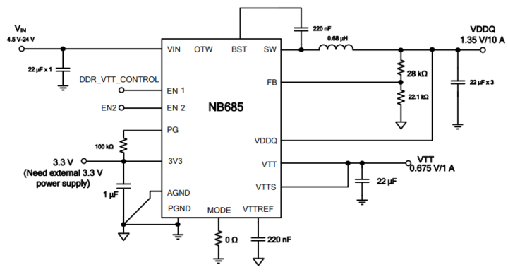
Why manufacturer sometimes use pariticular AGND and PGND for DC/DC?
Hi everyone, Sometimes I see separate AGND and PGND in DC/DC converters. But I don't understand how to connect them at the PCB level. I would appreciate it if you don't just tell me to check the manufacturer's documentation—I always do that. I just want to understand if everyone knows/understands the advantage of having separate AGND and PGND. And how to connect them at the PCB level? w/o AGND https://www.monolithicpower.com/en/documentview/productdocument/index/version/2/document_type/Datasheet/lang/en/sku/MPM3811GG-Z/?srsltid=AfmBOookF4rTW-Cev4suQY-0b8prv1BsC_usN-_Mg8VFNHBYDLx4vN_h w/ AGND https://www.monolithicpower.com/en/documentview/productdocument/index/version/2/document_type/Datasheet/lang/en/sku/NB685GQ/document_id/4378/
2 likes • Oct '25
Even though this conversation is a bit old, I’m new to the group and very interested in this topic because I also use these components and separate AGND and PGND on my PCBs — just like Nazar 😊 Normally, I design the PCB according to the datasheet, and yes, some datasheets recommend separating the ground regions. However, I’m a bit confused: when I design 4-layer or higher stack boards, I never separate the return plane (GND). But if I’m working on a 2-layer PCB and the datasheet explicitly suggests separating the grounds — should we still insist on keeping a solid return plane, or follow the datasheet recommendation? From my experience, keeping a solid return plane on 4-layer designs significantly improves EMI and signal integrity, but in 2-layer layouts it becomes more challenging to manage switching and analog return paths. Even though we know that 2-layer PCBs are not ideal for switching converters, sometimes we still need to design them due to cost or mechanical constraints.
1 like • Oct '25
Thanks a lot for your insights, Dario! I really appreciate your perspective and advice.
1-3 of 3

@gonul-demir-9611
An innovative professional with over a fourteen of experience in designing advanced electronic security systems and sensors sector.
Active 8h ago
Joined Oct 10, 2025