
Write something

22h •
My Why Behind WYP?
Six years ago, one simple question changed the direction of my life. "What's Your Passion?" It wasn't just a catchy phrase. It became a calling. At the time, I wasn't trying to build another media company. I simply wanted a place where real conversations could happen. A place where people could share their stories, their struggles, their victories, and the lessons they learned along the way. I started with a microphone, a camera, and my own story. I shared the challenges I'd faced throughout my life—the setbacks, failures, financial struggles, health battles, disappointments, and moments when I questioned everything. But I also discovered something powerful. Every person I met had a story. Every entrepreneur was fighting battles no one could see. Every business owner was asking many of the same questions. How do I grow? How do I get noticed? How do I create more cash flow? How do I build something that lasts? How do I live out the dream God placed in my heart? Those conversations changed me. I realized people don't just need marketing. They need encouragement. They need relationships. They need community. They need someone who believes in them before the world does. That realization is what transformed WYP. Today, WYP is no longer just a podcast. It's becoming a movement. A media platform. A networking community. A place where businesses, leaders, entrepreneurs, nonprofits, veterans, creators, and everyday people come together to help one another grow. Every day we're creating new opportunities... 🎙️ Podcasts 📸 Media 🤝 Networking Events 🎤 Speaking Opportunities 🎯 Business Exposure ❤️ Community Projects 🌎 Local & National Connections But at its core, our mission has never changed. People Helping People. That's it. Paying it forward. Because I believe something amazing happens when people stop competing and start collaborating. One introduction can change a business. One conversation can change a life. One opportunity can change a family's future.
1
0

4d •
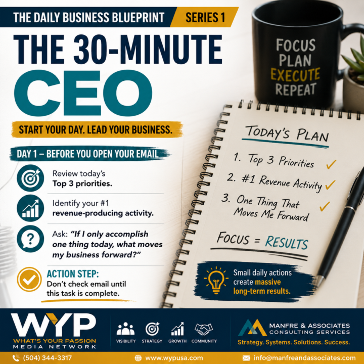
THE DAILY BUSINESS BLUEPRINT – DAY 1
The 30-Minute CEO Most business owners start their day the same way... Open email. Check social media. Put out fires. React to everyone else's priorities. By 10:00 AM, you've been busy... But have you actually moved your business forward? The most successful CEOs don't begin their day by reacting. They begin by leading. Before you open your inbox, take just 30 minutes and answer these three questions: What are my Top 3 priorities today? What is the ONE activity that will produce revenue? If I only accomplish one thing today, what will move my business forward the most? Then... Complete that ONE task before checking email. Here's the reality: Your inbox is everyone else's to-do list. Your calendar reflects your priorities. Your actions determine your results. Small daily decisions create massive long-term success. Lead your day... or your day will lead you. Question: What's the ONE thing you must accomplish today that will have the biggest impact on your business? #TheDailyBusinessBlueprint #CEO #Leadership #BusinessGrowth #SmallBusiness #Entrepreneur #Productivity #BusinessSystems #WhatsYourPassion #ManfreAndAssociates #DailyAction #Execution #SuccessSystems
5d •
Special Thank You To YOU !!!!
I want to provide my community with value. I know how it feels to strive and work long hours on a dream. This is why I built this community and all of the platforms and resources to help you. I have been in sales, management, leadership and have been making six figures since I was 28 years old. My mistakes. My sacrifices. My long hours. My secrets. I give them away as much as possible to inspire and offer a GPS to get through the overwhelming noise. If you have not Joined My DigitalPro Network Yet. This is your chance to gain ACCESS to more. Plus I personally want to offer you a 45 minute free discovery call to help you grow faster and all I ask is that you give me your testimony. https://www.digitalpronow.com/ I promise this to YOU. I am on a mission to create high income earners. I am not sure where you are today in your personal or business journey. My goal is to find out and help you achieve your next steps to achieving what you want. Take Me Up on My Offer. It's FREE. The challenge is that it's FREE. I DO NOT NEED TO OFFER IT FOR FREE. But I know for many times are tough. Let's Grow.

11d •
What's Stealing Your Time?
Some days, running a business feels less like leading a company... and more like running a circus. Before 9:00 a.m. you've already switched roles five times. 🎪 CEO 📞 Customer Service 💰 Accountant 👥 HR Manager 📣 Marketing Director 🛠️ Operations 💻 Technology Support Then someone tells you that you need to learn AI. Someone else says your website isn't optimized. Another promises they can double your leads. Meanwhile, payroll still has to be processed, customers still expect great service, and your team is looking to you for answers. I've spent nearly 30 years talking with business owners across dozens of industries, and one thing has become very clear: The businesses may be different, but the conversations are remarkably similar. Over the next several days, I'm launching a new series about the real challenges business owners face today—from marketing and AI to visibility, leadership, systems, employees, and building a business that doesn't run on chaos. This is a conversation, not a lecture. So let me ask you one question... What's stealing the most time from your business right now? Is it: - Marketing? - Employees? - Cash flow? - AI? - Sales? - Too many interruptions? - Something else? Drop your answer in the comments. I read every one, and your responses will help shape the next conversations in this series. FREE FRAMEWORK'S IN CLASSROOM. FOLLOW ME ON LINKEDIN Get Setup With Learning how you can get more visibility. Www.digitalpronow.com #BusinessOwner #Entrepreneur #Leadership #SmallBusiness #BusinessGrowth #Marketing #ArtificialIntelligence #AI #Systems #Productivity #Visibility #LinkedIn #BusinessStrategy #WYPMedia #ManfreAndAssociates

1-30 of 746
powered by

skool.com/whats-your-passion-1022
WYP community was developed to help facilitate people through the process on connecting their passions with the ability to grow and prosper.
Suggested communities
Powered by